기존에 사용하던 ST-LINK가 있었고, 새로 구매한 ST-LINK를 연결해서 테스트를 하려고 했는데, 다음과 같은 에러 메시지가 보인다. ST-LINK의 펌웨어도 업데이트를 해보았으나 동일한 메시지가 계속 발생.
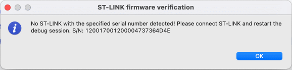
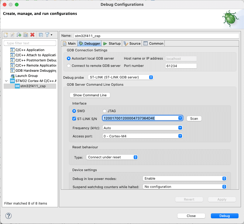
디버그 설정에서 보니 ST-LINK S/N 에서 Scan을 하면 자동으로 리스트가 업데이트가 되는 것이 아니라, 리스트 중에 하나를 수동으로 선택 해야하는 것.
 0 comments
 기존에 사용하던 ST-LINK가 있었고, 새로 구매한 ST-LINK를 연결해서 테스트를 하려고 했는데, 다음과 같은 에러 메시지가 보인다. ST-LINK의 펌웨어도 업데이트를 해보았으나 동일한 메시지가 계속 발생.
디버그 설정에서 보니 ST-LINK S/N 에서 Scan을 하면 자동으로 리스트가 업데이트가 되는 것이 아니라, 리스트 중에 하나를 수동으로 선택 해야하는 것.
0 comments 
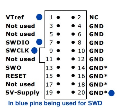
0 comments J-link 디버거의 SWD Pin map은 다음과 같다.
0 comments Bootloader 및 Application 펌웨어가 있는 경우 양산시 하나의 파일을 합쳐서 프로그래밍을 하면 1단계가 줄어든다.
srec_cat.exe 이라는 윈도우즈 프로그램을 사용하여 다음과 같이 하나의 파일로 합친다.
srec_cat.exe HexFile1.hex -Intel HexFile2.hex -Intel -o MergedHexFile.hex -Intel
:llaaaatt[dd...]cc
:10246200464C5549442050524F46494C4500464C33
This record is decoded as follows:
:10246200464C5549442050524F46494C4500464C33
|||||||||||                              CC->Checksum
|||||||||DD->Data
|||||||TT->Record Type
|||AAAA->Address
|LL->Record Length
:->Colon
Extended linear address records are also known as 32-bit address records and HEX386 records. These records contain the upper 16 bits (bits 16-31) of the data address. The extended linear address record always has two data bytes and appears as follows:
:02000004FFFFFC
When an extended linear address record is read, the extended linear address stored in the data field is saved and is applied to subsequent records read from the Intel HEX file. The linear address remains effective until changed by another extended address record.
The absolute-memory address of a data record is obtained by adding the address field in the record to the shifted address data from the extended linear address record. The following example illustrates this process..
Address from the data record's address field      2462
Extended linear address record data field     FFFF
                                              --------
Absolute-memory address                       FFFF2462
Extended segment address records-also known as HEX86 records-contain bits 4-19 of the data address segment. The extended segment address record always has two data bytes and appears as follows:
:020000021200EA
When an extended segment address record is read, the extended segment address stored in the data field is saved and is applied to subsequent records read from the Intel HEX file. The segment address remains effective until changed by another extended address record.
The absolute-memory address of a data record is obtained by adding the address field in the record to the shifted-address data from the extended segment address record. The following example illustrates this process.
Address from the data record's address field     2462
Extended segment address record data field      1200
                                             --------
Absolute memory address                      00014462
Start linear address records specify the start address of the application. These records contain the full linear 32 bit address. The start linear address record always has four data bytes and appears as follows:
:04000005000000CD2A
The Start Linear Address specifies the address of the __main (pre-main) function but not the address of the startup code which usually calls __main after calling SystemInit(). An odd linear start address specifies that __main is compiled for the Thumb instruction set.
The Start Linear Address Record can appear anywhere in hex file. In most cases this record can be ignored because it does not contain information which is needed to program flash memory.
:00000001FF
Following is an example of a complete Intel HEX file:
:10001300AC12AD13AE10AF1112002F8E0E8F0F2244
:10000300E50B250DF509E50A350CF5081200132259
:03000000020023D8
:0C002300787FE4F6D8FD7581130200031D
:10002F00EFF88DF0A4FFEDC5F0CEA42EFEEC88F016
:04003F00A42EFE22CB
:00000001FF
참고
0 comments 0 comments 2년전에 작업한 Mac OS X에 nRF51 개발 환경 설정하기 포스팅을 보면서 nRF52 환경을 설정하다가 달라진 점이 있어서 다시 쓰게된 포스팅.
개념은 다음과 같다. 1) gcc 와 툴체인 설치 2) OSX용 nRF5x Command Line Tools 설치 3) SDK 설치. 이 과정에서 gcc 실행파일 위치를 bash_profile에 입력하고, SDK의 gcc 컴파일 설정을 이에 맞게 하면 된다.
여기에서 최신 버전 다운로드 및 다음과 같이 압축을 푼다. 설치 위치는 크게 중요하지 않다. 만약 이전에 설치를 했을 경우 ~/usr/local/bin 아래 설치를 했을 수도 있음.
$ mkdir /usr/local/
$ tar -xjf gcc-arm-none-eabi-8-2019-q3-update-mac.tar.bz2 -C /usr/local/
위 gcc경로와 nrfjprog, mergehex의 경로를 bash_profile 입력한다.
export PATH=/usr/local/gcc-arm/gcc-arm-none-eabi-8-2019-q3-update/bin:$PATH
export PATH=/usr/local/bin:/usr/local/sbin:/usr/local/nrfjprog:$PATH
components/toolchain/gcc/Makefile.posix 파일을 다음과 같이 수정한다. GNU_VERSION은 다음과 같이하면 알 수 있다.
$ arm-none-eabi-gcc –version
GNU_INSTALL_ROOT := /usr/local/gcc-arm-none-eabi-8-2019-q3-update/bin/
GNU_VERSION := 8.3.1
GNU_PREFIX := arm-none-eabi
example 폴더의 예제를 컴파일 및 다운로드 해 본다. 참고로 PCA10040 보드가 nRF52832칩을 사용한 보드이니 이 에제를 사용해야 함.
$ make
$ make flash
0 comments 소프트뱅크가 arm을 인수후 2017년에 발간된 arm의 백서 – The route to a trillion devices
2035년에는 1조개의 IoT 디바이스가 사용될 것이라는 전망
By 2035, the technology companies that sell IoT hardware and services could be serving a market worth a trillion dollars per annum. That is an exciting figure, but an even greater value will flow to the companies that utilize the information collected by those systems, and to the consumers who will benefit from widespread efficiency gains across the economy.
0 comments 구글 크롬 65버전 이상일 경우 WebUSB를 지원한다.
Micro:bit의 경우 웹에서 MakeCode같은 프로그램으로 코딩을 하고 hex 파일을 다운로드 후 외장 디스크로 연결된 디바이스에 drag & drop를 해서 프로그래밍을 했는데, 이제는 웹브라우저에서 바로 USB를 통해 프로그래밍이 가능하다.
아두이노의 경우 다음과 같이 작업을 한다.
https://www.hackster.io/FreeGroup/arduino-webusb-circuit-simulator-fun-9c841a
0 comments OpenSDA는 open-standard 시리얼 디버거 어댑터로 MSD Bootloader 및 USB CDC기능을 가진다.
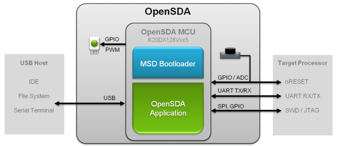
NXP, Freescale사의 보드의 경우 P&E micro사의 솔루션이 들어가 있는데 보드에 오래된 bootloader가 들어가 있으면 업데이트를 해야하며 다음과 같은 순서로 업데이트를 한다. 어떤 OS에서는 캐쉬기능 때문에 파일을 넣어도 write가 안된 경우도 있고, Windows8, Windows 10에서 문제가 있다고 하기도 함.
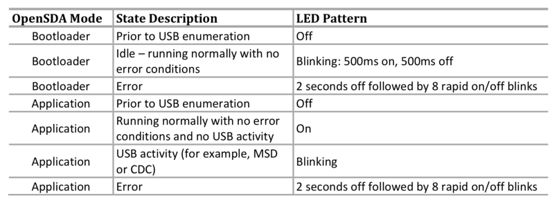
보드의 LED는 다음과 상태값을 가진다.

https://mcuoneclipse.com/2014/11/01/illustrated-step-by-step-instructions-updating-the-freescale-freedom-board-firmware/
https://mcuoneclipse.com/2016/06/26/how-to-recover-the-opensda-v2-x-bootloader/
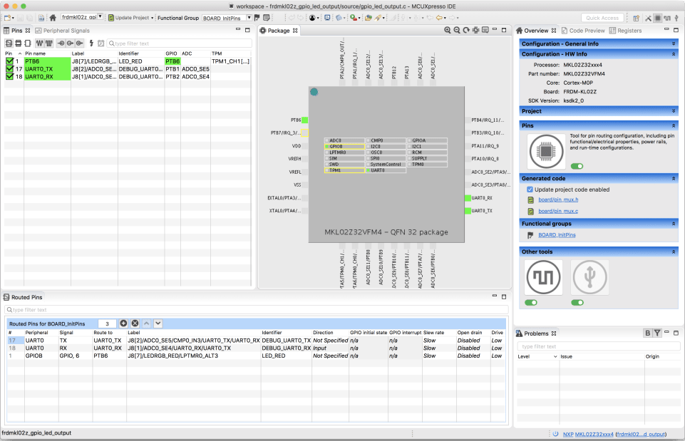
0 comments MCU 벤더들에서 제공하는 무료툴들은 대부분 이클립스 기반의 툴을 수정해서 제공을 한다. 그래서 하나의 툴에 익숙하면 다른 툴도 쉽게 쓸 수 있지만 다른 기능들은 메뉴얼을 보면서 익혀야 한다. NXP사의 MCUXpresso도 약간 특이한 점이 있어서 정리.
1. 먼저 회원가입을 하고, https://mcuxpresso.nxp.com/en/dashboard 에서 보드나 칩을 선택해서 설정을 한후 SDK파일을 다운로드 받는다.

2. MCUXpress에서 Installed SDKs에 이 파일을 Drag & Drop한 후 좌측의 Import SDK examples를 클릭한다.

3. 보드, 칩을 선택하고 Next 버튼을 클릭

4. 원하는 예제를 선택하면 관련 코드가 import된다.

참고로 MCUXPresso Config Tools도 내장이 되어 있어서 pin, clock설정이 가능하다.

관련 메뉴얼 – Getting Started with MCUXpresso SDK