:::: MENU ::::

GUI 프로그램 솔루션

PC에서 GUI 프로그램을 만들 수 있는 툴은 많지만 그중에서 맥, 윈도우즈, 리눅스등 멀티 플랫폼을 지원하는 툴중에서 라이브러리 지원이 잘 되어 있고 많이 사용되는 툴은 Qt와 openframworks 인 것 같다. 둘다 C++ 인테 Qt의 경우 PyQt 또는 PySide로 파이썬으로 개발이 가능하다.
그리고 Qt Designer로 GUI를 설계하고 파이썬 코드에서 불러와서 사용이 가능하다. Qt Designer는 윈도우즈의 경우 아나콘다가 설치되면 같이 설치되지만 맥에서는 그렇지 않아서 https://build-system.fman.io/qt-designer-download 에서 다운로드 가능한다.


블루투스 관련된 라이브러리

GUI 관련 예제

GUI 관련된 예제들은 기본적인 것만 확인하고 필요한 것이 있을때 참고하면 된다.

Qt Designer 관련 참고


Google fit, Apple HealthKit으로 부터 Health data 가져오기

Google Fit

여기에서 안드로이드 API나 REST API 관련 내용을 확인 가능

다음 4가지 데이터를 얻을 수 있음 (퍼미션 필요함)

  • Activity & Exercise — step count, burned calories, workout duration, basal metabolic rate, steep data.
  • Location — total running/cycling distance and speed as well as cycling cadence (RPM).
  • Body — heart rate, weight, body fat percentage.
  • Nutrition — food & hydration.

다음의 데이터는 OAuth가 필요함

  • Oxygen saturation
  • Body temperature
  • Blood pressure
  • Blood glucose
  • Cervical position and others

이런 데이터를 사용하는 것에 대한 Term & Condition

이중 몇가지 사항은
– Google Fit API를 사용한다고 해서 앱이 자동으로 HIPAA를 준수하는 것은 아니다..
– Google 피트니스에서 얻은 어떠한 콘텐츠도 판매하지 않으며 최종 사용자가 판매하도록 허용하지도 않는다.

Apple’s HealthKit

Apple은 개발자가 사용할 수 있는 총 3개의 키트를 제공

  • HealthKit — 건강 및 피트니스 데이터 컨테이너. 다른 앱과의 원활한 통신을 가능하게 하고 건강 데이터를 쉽게 저장, 교환 및 수집할 수 있도록 한다.
  • ResearchKit — 이 프레임워크는 연구 목적으로 많은 사람들로부터 의료 데이터를 수집해야 하는 경우에 유용함
  • CareKit — 장기 및 만성 질환 모니터링 및 관리, 수술 후 회복 등을 위한 프레임워크
  • 애플이 구글보다 더 많은 데이터를 모으고 있는데 full list는 여기에서 확인 가능하다.
  • Official pages of the iOS HealthKit framework

Garmin

Fitbit

STRAVA

Thryve

  • 찾아보니 애플, 구글, 삼성등의 디바이스로 부터 데이터를 가져와서 개발을 해주는 라는 회사가 있는데, “Get access to Thryve’s SDK and integrate 500+ wearables with your app” 이런 캐치프레이즈를 내걸고 있다.
  • https://thryve.health/api-doc/index.php#introduction

참고


ST-LINK가 STM32CubeIDE에서의 오류

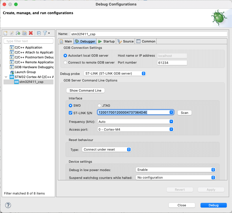
기존에 사용하던 ST-LINK가 있었고, 새로 구매한 ST-LINK를 연결해서 테스트를 하려고 했는데, 다음과 같은 에러 메시지가 보인다. ST-LINK의 펌웨어도 업데이트를 해보았으나 동일한 메시지가 계속 발생.

디버그 설정에서 보니 ST-LINK S/N 에서 Scan을 하면 자동으로 리스트가 업데이트가 되는 것이 아니라, 리스트 중에 하나를 수동으로 선택 해야하는 것.


BLE over UART throughput

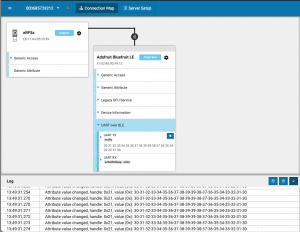
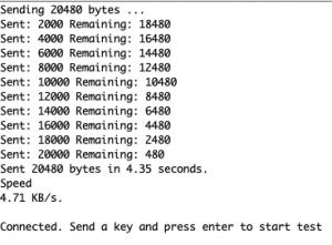
Adafruit사의 Feather m0 bluefruit 보드의 UART to BLE Throughput 측정. PC측에는 nRF Connect 앱인 BLE 앱을 사용함.

이 앱에서 연결을 하고 데이터를 수신한다. 보내는 측의 로그를 확인하면 대략 4.71KB/S 정도 나오는데, 핸드폰 앱에서 확인해보니 4KB/S 정도 나옴.

성능도 중요하지만 무선이므로 데이터 손실이 없을 수 없으며, 찾아보니 그 이유중 하나는 다음과 같다. (출처 – https://interrupt.memfault.com/blog/ble-throughput-primer)

Counterintuitively, even though the Link Layer of BLE is reliable, packet loss is still something to be concerned about for BLE. This is because many many stacks drop data within the software stack. For example, BLE messages get queued up in the stack and when the heap holding the packets runs out of memory, some stacks will silently drop data. This means if you are sending large amounts of data over BLE you will usually want to add some sort of reliability layer that can detect & retransmit messages when data is dropped. The way this is implemented can have sizeable impacts on throughput. For example, if you have designed your own protocol on top of L2CAP or GATT and every message sent requires an acknowledgement before another message is sent, you’ll typically wind up adding a connection interval worth of latency getting the data sent out, effectively halving the max throughput which can be achieved.

즉 BLE Link Layer는 reliable하지만 BLE stack에서 힙의 메모리가 부족할 때 일부 스택은 자동으로 데이터를 삭제된다. 따라서 상위레벨의 프로토콜에서 재전송 기법을 사용해야 함.

Mitigation of Data Packet Loss in Bluetooth Low Energy-Based Wearable Healthcare Ecosystem 이 문서의 내용 참고


RF에서 RX Sensitivity 란?

RX Sensitivity
– 수신기가 감지할 수 있는 최소 신호 강도를 측정한 것. 즉 식별이 가능하고, 처리할 수 있는 가장 약한 신호를 알려준다.
– RX Sensitivity는 dBm으로 표시
– 신호의 미약한 정도를 나타내므로 신호의 전력 레벨이 낮을수록 좋다.
– 예를 들어 -90dBm의 수신기 감도는 -80dBm보다 낫다. 즉, -90dBm 수신기가 더 민감하고 더 낮은 전력 신호를 해석할 수 있음을 의미한다.

Receiver Sensitivity Requirements for modules:
– LoRa: up to -130 dBm
– Cellular: up to -120 dBm
– Bluetooth: -70 dBm to -100 dBm
– ZigBee: -85 to -92 dBm
– Wi-Fi: -40 dBm to -80 dBm

TX Power
TX Power는 worst-case에서도 적어도 이 정도의 전송 전력을 보장한다는 수치이다.


nRF52 Segger Embedded Studio 설정 – CMSIS Configuration Wizard

노르딕에서 제공하는 예제코드의 경우 SDK 설정이 sdk_config.h에서 이루어 진다. 문제는 이 파일의 사이즈가 크고 #ifdef 등으로 설정이 되어 있어서 파일 자체를 보기가 불편하다. 그래서 이 설정을 쉽게 하는 툴이 제공이 되는데, 기본 SES 설정에는 없어서 따로 설정을 해야 한다.

  1. Go to File -> Open Studio Folder… -> External Tools Configuration.
  2. The tools.xml file will be opened in the editor.

다음의 코드를 삽입한다

<item name=“Tool.CMSIS_Config_Wizard” wait=“no”>
     <menu>&amp;CMSIS Configuration Wizard</menu>
     <text>CMSIS Configuration Wizard</text>
     <tip>Open a configuration file in CMSIS Configuration Wizard</tip>
     <key>Ctrl+Y</key>
     <match>*config*.h</match>
     <message>CMSIS Config</message>
     <commands>
         java -jar &quot;$(CMSIS_CONFIG_TOOL)&quot; &quot;$(InputPath)&quot;
     </commands>
</item>

참고 – https://infocenter.nordicsemi.com/index.jsp?topic=%2Fcom.nordic.infocenter.sdk5.v15.0.0%2Fsdk_config.html


ESP 빌드시 문제 해결

ESP32 가 빌드는 되는데 flashing이 다음과 같은 에러메시지로 안되는 경우

Traceback (most recent call last):
File “esptool.py”, line 57, in <module>
File “/Library/Python/2.7/site-packages/PyInstaller/loader/pyimod03_importers.py”, line 389, in load_module
File “serial/tools/list_ports.py”, line 29, in <module>
File “/Library/Python/2.7/site-packages/PyInstaller/loader/pyimod03_importers.py”, line 389, in load_module
File “serial/tools/list_ports_posix.py”, line 31, in <module>
File “/Library/Python/2.7/site-packages/PyInstaller/loader/pyimod03_importers.py”, line 389, in load_module
File “serial/tools/list_ports_osx.py”, line 32, in <module>
ValueError: dlsym(RTLD_DEFAULT, kIOMasterPortDefault): symbol not found
Failed to execute script esptool

기존 esptool을 esptool.py로 다음과 같이 변경을 하면 해결이 된다.

copy /Users/XXXXX/Library/Arduino15/packages/esp32/hardware/esp32/1.0.4/tools/esptool.py
to /Users/XXXXX/Library/Arduino15/packages/esp32/tools/esptool_py/2.6.1/esptool.py

chmod +x esptool.py

그리고 /Users/XXXXX/Library/Arduino15/packages/esp32/hardware/esp32/1.0.4/platform.txt 파일을 열어서 다음과 같이 수정한다.
tools.esptool_py.cmd=esptool -> tools.esptool_py.cmd=esptool.py

platform.txt 파일을 수정하고 Arduino를 재시작


ECG – ADS1292 module test

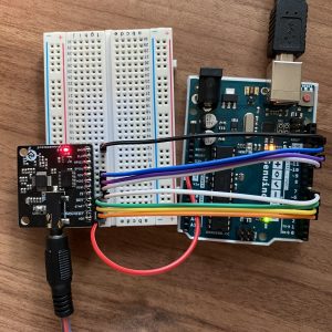
심장의 ECG신호를 측정할 수 있는 ADS1292모듈을 테스트해 봤다. 먼저 Arduino Uno를 가지고 테스트를 해서 신호가 제대로 나오는 지를 확인한다.


신호의 출력값은 Arduino Plotter를 이용해서 확인을 한다. 다음 스텝은 이 값을

1) SeeedStudio 의 Wio Terminal같은 디스플레이가 있는 디바이스에서 진행을 하거나,

2) 출력값을 BLE를 이용해 웹에서 Plot을 하거나

3) WiFi를 이용해서 서버에서 데이터를 받아서 디스플레이를 하는 3가지 형태로 진행을 할 예정~


SPI 핀 네이밍

마스터, 슬레이브의 이름에서 주는 주종관계 때문에 그동안 별 의식없이 쓰여왔던 이름들이 바뀌었다.

MOSI – COPI

MISO – CIPO

이 2가지만 기억하면 될 것 같다.

New signal names:

  • SDO – Serial Data Out. An output signal on a device where data is sent out to another SPI device.
  • SDI – Serial Data In. An input signal on a device where data is received from another SPI device.
  • CS – Chip Select. Activated by the controller to initiate communication with a given peripheral.
  • COPI (controller out / peripheral in). For devices that can be either a controller or a peripheral; the signal on which the device sends output when acting as the controller, and receives input when acting as the peripheral.
  • CIPO (controller in / peripheral out). For devices that can be either a controller or a peripheral; the signal on which the device receives input when acting as the controller, and sends output when acting as the peripheral.
  • SDIO – Serial Data In/Out. A bi-directional serial signal.

Deprecated signal names:

  • MOSI – Master Out Slave In
  • MISO – Master In Slave Out
  • SS – Slave Select
  • MOMI – Master Out Master In
  • SOSI – Slave Out Slave In

Signal names unchanged:

  • SCK – Serial Clock. The clock for the bus generated by the controller.

Pages:1234567...56