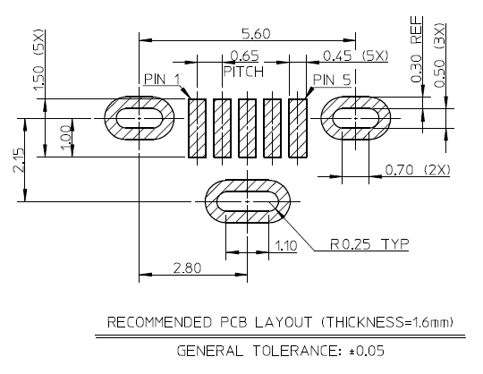
PCB 레이아웃 설계시 PCB house에서 지원하는 규격내에서 설계를 하는 것이 바람직하다.

추가적인 내용은 한샘디지텍 참고.
Safety Capacitor, 보통 X,Y Capacitor로 부르며, 안전을 위해 AC 전원 라인에 사용되고, X, Y 2가지 타입이 있다. 일반적으로 X2, Y2를 많이 사용한다.
When a Class-X capacitor, also referred to as an “across the line capacitor”—the capacitor placed between line and neutral—fails because of an overvoltage event, it is likely to fail short. This failure, in turn, would cause an overcurrent protective device, like a fuse or circuit breaker, to open. Therefore, a capacitor failing in this fashion would not cause any electrical shock hazards.
If a Class-Y capacitor, also known as the “line to ground capacitor” or “the line bypass capacitor”—the capacitor placed between line and ground—fails short, this could lead to a fatal electric shock due to the loss of the ground connection. Class-Y safety capacitors are designed to fail open. A failure will cause your electronic device to be subjected to the noise and interference that the capacitor would normally filter out, but at least there will be no fatal electric shock hazard.

참고
PCB Panelization & Bridge design 관련 잘 정리된 자료.
기존에 미싱홀이라고 부르던 것이 해외에서는 stamp hole이라고 부른다.
http://www.seeedstudio.com/blog/2017/05/10/panelization-and-bridge-design/
그리고 아래 링크는 PCB DFM 관련 가이드

https://statics3.seeedstudio.com/fusion/ebook/PCB+DFM+V1.0+.pdf


Routing 과 Milling의 차이
“Routing” describes the cutting of the board profile, outline or contour. We use a 2 mm cutter for this. Any feature which can be cut with the 2 mm cutter is part of the profile.
“Milling” refers to any slots or cut-outs inside the PCB, but also to any slots in the profile of the PCB which can’t be cut with a 2 mm cutter.
즉 라우팅은 2mm 커터로 보드의 외곽을 자르는 것이고, 밀링은 보드 안쪽에 있는 cut-out 또는 슬롯을 더 작은 툴로 작업을 하는 것이다.
보드에 슬롯을 만드는 법
일반적이지 않기 때문에 PCB 업체에서 작업을 빠트릴 수 있다. 따라서 따로 알려주고, 0.50 mm 라인으로 작업을 하는데 Eagle CAD에서는 Eagle CAD에서는 Milling Layer 46에 작업을 한다.
하지만 PCB 업체에 따라서 이 작업이 안될 수 도 있다.
참고
http://docs.oshpark.com/submitting-orders/cutouts-and-slots/
http://www.eurocircuits.com/blog/158-Slots-and-cut-outs
이글캐드에서 장홀(plated slot) 만들기

드릴을 중첩적으로 배치하면 돼지만 DRC에서 에러가 난다. 관련 자료
방법은 위의 슬롯만들기와 동일하게 Milling 레이어에서 작업을 하고, 업체에 얘기를 해야 한다. ㅠㅠ
참고
http://electronics.stackexchange.com/questions/198590/how-to-add-holes-in-package-and-create-elongated-plated-holes-eagle
http://electronics.stackexchange.com/questions/202551/eagle-oval-pad
https://www.autodesk.com/products/eagle/blog/what-you-didnt-know-about-eagle-slotted-holes/
아두이노 보드의 모델명 같은 것은 일반 실크가 아닌 네거티브 실크로 되어 있다. Eagle Cad에서 이 작업을 하려면 negasilk.ulp를 사용하면 되는데 방법은 다음과 같다.
https://www.youtube.com/watch?v=lVpzqZfN2A4
이외에 PCB를 예쁘게 만들기 위해 BMP 이미지를 불러올 수도 있고, DXF를 불어와서 작업을 할 수도 있다. 이것을 위해서는 https://todbot.com/blog/2011/06/06/from-illustrator-to-eagle-vector-graphics-in-circuits/를 참고.
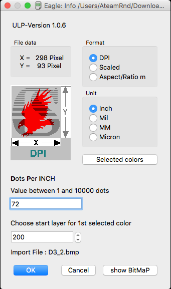
예전에 포스팅한 글 “Eagle CAD로 작업한 PCB에 이미지 파일 넣기“에 대한 추가적인 정보. 보드에 넣을 이미지의 사이즈를 DPI로 맞추고 실제 이미지의 DPI의 배수로 맞추면 편하다.
아래 그림은 72DPI로 작업한 이미지를 실제 사이즈에 맞추기 위한 설정

Eagle PCB에서 centroid-screamingcircuits-smd.ulp를 실행시킨다. 그러면 csv파일이 생긴다. 이파일은 inch단위의 파일이 생성된다. 만약 mm 단위의 파일이 필요하면 Mountsmd.ulp를 사용한다.
Allegro PCB에서는 File > Placement… 를 실행한다.

Analog Engineer’s Pocket Reference Guide 4th Edition (Rev. B)
전자과에서 배우던 내용인데, 실제적인 것이 많아서 유용함.
이 링크에 비디오도 있다.
아날로그와 디지털이 같이 있는 회로를 PCB 디자인 할때 필요한 사항
• Do not split the ground plane, use one solid plane under both analog and digital sections of the board
• Use large area ground planes for low impedance current return paths
• Keep over 75% board area for the ground plane
• Separate analog and digital power planes
• Use solid ground planes next to power planes
• Locate all analogue components and lines over the analogue power plane and all digital components
and lines over the digital power plane
• Do not route traces over the split in the power planes, unless if traces that must go over the power
plane split must be on layers adjacent to the solid ground plane
• Think about where and how the ground return currents are actually flowing
• Partition your PCB with separate analog and digital sections
• Place components properly