한번에 찾기 힘들어서…
May 29, 2018 |
 0 comments
0 comments 0 comments 한번에 찾기 힘들어서…
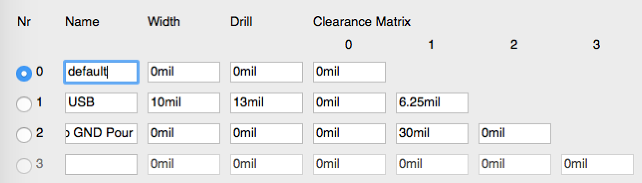
0 comments The first step is to create and set net classes. In EAGLE go to Edit->Net classes. There you can create different values for trace width and clearance. Differential pairs should have quite a big clearance to copper pours (2-3 times the track width). Therefore I entered two net classes, one for USB (#1) and one for the top copper pour (#2) as my USB signal is routed on the top layer. As you can see I entered the values from the impedance calculator in net class #1. 10mil for track width. In Clearance Matrix you tell EAGLE how much clearance the different net classes will be used by the Auto Router or differential pair routing. These settings tell EAGLE that USB traces should be separated by 6.25mil and that USB traces should have a clearance of 30 mil to the traces (copper pours) set to net class #2.
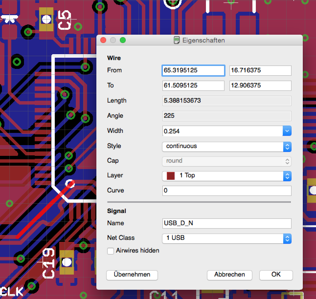
In the next step you have to set the net classes of the traces. I selected each of both USB traces one after the other and set the USB net class in the bottom area of the Info dialog window. Don’t forget to set the Top GND net class to the polygon forming the top copper pour. If you don’t have a top copper pour you don’t need to do that.
참고: http://www.appfruits.com/2015/03/building-your-own-custom-teensy/
0 comments 
http://fritzing.org/fritzings-graphic-standards/download-fonts-and-templates
brew install qt
cd eagle2fritzing/brd2svg
qmake -spec macx-g++ brd2svg.pro
make
clang: error: linker command failed with exit code 1 (use -v to see invocation)
이런 에러가 발생하면, make파일에서 링크옵션에서 static을 제거하면 된다.
LFLAGS =
-static -static-libgcc -static-libstdc++-headerpad_max_install_names $(EXPORT_ARCH_ARGS) -Wl,-syslibroot,/Applications/Xcode.app/Contents/Developer/Platforms/MacOSX.platform/Developer/SDKs/MacOSX10.13.sdk -mmacosx-version-min=10.10 -Wl,-rpath,@executable_path/Frameworks
FOO
|– brds
|– board1.brd
|– board2.brd
|– board3.brd
0 comments 이전에 작성한 포스팅 Eagle CAD에서 거버 만들기는 일반적으로 2층 PCB의 경우 bottom에 부품이 없을 경우를 가정한다. 만약 bottom면에 부품을 실장을 하거나, PCB에 이미지를 넣을 경우는 기본으로 설정된 레이어 이외의 레이어를 사용하므로, 거버를 만들때 추가적인 레이어가 선택이 되도록 해야 한다.
Bottom면에 부품을 실장할 경우는 Silk screen solder를 추가한다. 즉 거버파일을 만드는 단계에서 gerb274x.cam를 선택하고 작업을 할때 Silk screen SOL을 만들고 파일 확장자는 *.pls로 해서 작업을 하면 된다.

이렇게 할 경우 최종 거버파일은 10개가 된다.
그리고 만들어진 거버데이터는 반드시 확인하기~~
Eagle CAD 8.6 이후부터는 거버파일 만들기가 더 쉬워짐: 이 내용 참고