:::: MENU ::::

BBC micro:bit 분석

BBC micro:bit는 영국에서 컴퓨터 교육용으로 디자인된 마이크로컨트롤러 보드이다.

개발에 참여한 파트너사들

하드웨어

  • 메인 MCU: ARM CortexM0 코어에 블루투스 LE 내장된 노르딕사의 nRF51822 (256KB flash, 16KB SRAM)
  • 인터테이스 : USB 2.0 OTG 내장된 NXP KL26Z (CortexM0+) DAPLink를 제공하여, 가상 USB 플래시 드라이브를 제공해서 펌웨어 업데이트를 가능하게 하며, USB 파워를 받아서 전압 레귤레이터의 역할. 관련 포스팅
  • 3 가속도 : NXP MMA8652, 메인 MCU I2C 연결
  • 3 지자기센서 : NXP MAG3110, 메인 MCU I2C 연결
  • 5×5 LED 어레이
  • 2개의 버튼

핀아웃

소프트웨어

모두다 브라우저기반의 컴파일러를 제공하며, 난이도에 따라 아래 그림 처럼 3가지로 나뉠 수 있다.

아키텍처

기타

관련자료


Nabto 사용법

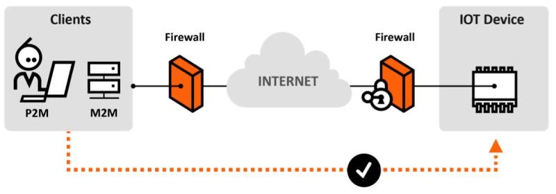
Nabto provides a full communication infrastructure to allow real-time direct, encrypted communication between end-user clients (tablets, smartphones, PC) and resource limited devices (< 1kb RAM and up) – the Nabto communication platform. The platform provides direct real-time connectivity with no firewall or dynamic IP hassle – just as you know from e.g. Skype™.

Nabto 사용법

Nabto 디바이스 포털 https://developer.nabto.com/) 에서 ID를 등록하고 Add Device에 디바이스 이름을 입력후 디바이스를 추가한다. 이 디바이스 ID는 xxxx.demo.nab.to 이런 형태가 된다.

그러면 디바이스의 status가 나오고 Key가 할당이 된다. 이 Key는 보안 연결에 사용이 되며 HTML-DD는 HTML Device Driver로 web GUI를 포함하는데 default를 사용한다.

uNabto SDK(unabto_sdk.zip)를 다운로드 후 압축을 풀고 다음과 같이 빌드를 한다.

cd unabto_sdk/unabto/apps/pc_demo/
cmake .
make

이렇게 하면 pc_demo 라는 실행파일이 생성이 되는데 다음과 같이 디바이스 이름과 Key를 입력하여 실행을 한다.

./pc_demo -d [xxxx.demo.nab.to] -s -k [KEY]

아래는 jbtest2.demo.nab.to로 실행을 한 결과인데 마지막에 연결 상태가 WAIT_GSP to ATTACHED가 되어야 한다.

16:47:23:876 unabto_main.c(41) Identity: ‘jbtest2.demo.nab.to’
16:47:23:876 unabto_main.c(42) Program Release 2.21889
16:47:23:876 unabto_main.c(43) Buffer size: 1500
16:47:23:876 unabto_common_main.c(127) Device id: ‘jbtest2.demo.nab.to’
16:47:23:876 unabto_common_main.c(128) Program Release 2.21889
16:47:23:879 unabto_app_adapter.c(698) Application event framework using SYNC model
16:47:23:885 unabto_context.c(55) SECURE ATTACH: 1, DATA: 1
16:47:23:885 unabto_context.c(63) NONCE_SIZE: 32, CLEAR_TEXT: 0
16:47:23:885 unabto_common_main.c(206) Nabto was successfully initialized
16:47:23:885 unabto_context.c(55) SECURE ATTACH: 1, DATA: 1
16:47:23:885 unabto_context.c(63) NONCE_SIZE: 32, CLEAR_TEXT: 0
16:47:23:886 unabto_attach.c(787) State change from IDLE to WAIT_DNS
16:47:23:886 unabto_attach.c(788) Resolving dns: jbtest2.demo.nab.to
16:47:24:411 unabto_attach.c(809) State change from WAIT_DNS to WAIT_BS
16:47:24:424 unabto_attach.c(292) Sending INVITE to Base Station: 1
16:47:24:725 unabto_attach.c(474) State change from WAIT_BS to WAIT_GSP
16:47:24:736 unabto_attach.c(303) Sending INVITE to GSP: 1
16:47:24:736 unabto_attach.c(266) ######## U_INVITE with LARGE nonce sent, version: – URL: –
16:47:25:084 unabto_attach.c(624) nmc.ctx.privat : 0.0.0.0:53538
16:47:25:085 unabto_attach.c(625) nmc.ctx.global : 210.113.20.1:53538
16:47:25:086 unabto_attach.c(573) GSP-ID(nsi): 3148170758
16:47:25:086 unabto_attach.c(575) State change from WAIT_GSP to ATTACHED

디바이스 포털에서 디바이스의 상태가 Offline에서 Online으로 바뀐 것을 볼 수 있다.

Nabto app이나 브라우져(브라우저는 IE나 Firefox만 지원하며 플러그인을 설치해야 한다.)에서 nabto://디바이스이름.demo.nab.to를 실행한다.


데모웹에서 스위치를 on/off하면 실행시킨 터미널에서 메시지를 볼 수 있다.

Arduino에서 테스트하는 방법

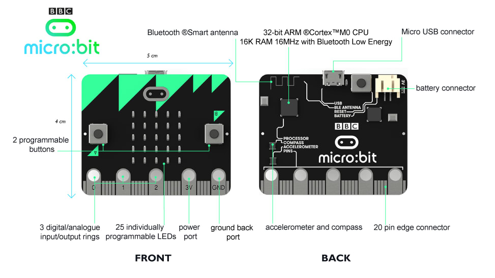
아두이노와 네트워크 연결을 위한 Ethenet 쉴드가 필요하다.

  1. Copy the unabto/apps/arduino/Nabto directory from the SDK to the Arduino libraries directory. On Windows it is normally located in My Documents\Arduino\libraries\ and on Mac/Linux it is located in ~/Documents/Arduino/libraries/.
  2. Open Arduino.
  3. Open Files → Examples → Nabto → Demo.
  4. Type in the MAC-address located on the bottom of the Ethernet shield.
  5. Specify an unique ID for the Arduino demo, e.g <macaddress>.sdk.u.nabto.net.
  6. Connect the LED to pin A0 (anode) and ground (cathode).
  7. Click on Tools → Board and make sure you have the right board chosen.
  8. Click upload.
  9. Open Firefox or Internet Explorer and type in the ID.

Github에 100MB 이상 파일 올리는 법

Github은 100MB이상의 파일을 올리지 못하게 되어 있는데, 해결 방법은 git-lfs를 설치해서 올리면 된다.

git-lfs를 설치
https://git-lfs.github.com/ 에서 파일을 다운로드하고 install.sh 를 실행한다.
git lfs install을 실행해서 설치가 제대로 됐는지 확인한다.

git lfs install

github에 올릴 파일을 등록한다.

git lfs track “*.xxx”

그 다음은 똑같다.

git add *.xxx
git commit -m “Add design file”
git push origin master


PID 튜닝

Reprap 기반의 코드에 적용되어 있는 PID 를 튜닝하는 방법은 다음과 같이 PID Auto-tune을 사용해서 상수값 Kp, Ki, Kd값을 정하고 Configuration.h에 설정을 한다.

M303 E0 S210 C8

위 코드의 의미는 타겟온도 210도로 하고 8번의 사이클을 거쳐서 값을 정하는것. 그러면 다음과 같이 값이 나온다.

bias: 92 d: 92 min: 196.56 max: 203.75
Ku: 32.59 Tu: 54.92
Clasic PID
Kp: 19.56
Ki: 0.71
Kd: 134.26
PID Autotune finished ! Place the Kp, Ki and Kd constants in the configuration.h

Configuration.h 파일에 설정후 컴파일을 하는 대신에 다음과 같이 M301커멘드로 테스트가 가능하다.

M301 P19.56 I0.71 D134.26

PID Auto-tune

  • The PID test doesn’t use a PID control loop to control the temperature! It shouldn’t matter what values you have stored when you run the autotune. Instead, the autotune function runs the heater in “bang-bang” mode, leaving the heater on for an extended period of time, and then off for an extended period of time, and simply observing the thermal behavior in response to heating and cooling.
  • Each cycle in the autotune run is a test where the controller cycles the heater, intentionally overshooting the target value for 5 seconds and observing how far up it goes, and how long it takes to coast back down to the target temperature. Once below the target temperature for 5 seconds, it observes how far the temp fell, and then cycles the heater on for another run at the target.
  • The first three cycles calculate a “bias” to dial in the level of maximum power that will be used for the remainder of the cycle/tests. You will get to see those bias numbers, but there’s not much you can do with them. You will not get PID parameters from these initial cycles.
  • The fourth and subsequent tests still overshoot by 5 seconds and undershoot by 5 seconds, but this time the observed duration of the heat cycle, and the min and max temperatures reached, are put through the mathematical formulas described in the Ziegler–Nichols PID tuning method. This is a mathematical way to determine PID constants that perform acceptably in many systems. Values for the three parameters Kp, Ki, and Kd will be displayed for the cycle, and a new cycle will begin.
  • After all the test cycles are finished, you can average the values you get from each of these cycles and use those as your baseline parameters.

Kp, Ki, Kd의 의미

  • The proportional (P) constant Kp is in counts/C, representing the change in the softPWM output per each degree of error.
  • The integral (I) constant Ki in counts/(C*s) represents the change per each unit of time-integrated error.
  • The derivative (D) constant Kd in counts/(C/s) represents the change in output expected due to the current rate of change of the temperature.
  • Kp is the “proportional” term. The further off target you are, the more power this term contributes.
  • Ki is the “integral” term. This term contributes more control input as the accumulated offset over time between measured and target temperatures increases. In other words the longer you’ve been off target, the more input this term will contribute in the direction of the target (could be more or less heater power).
  • Kd is the “derivative” term. This term allows the controller to “predict” or look ahead of the current temperature to slow the rate of change down and let the measured temperature creep up on the target. Mathematically speaking it attempts to minimize the slope of the temperature curve with respect to the target.

수동으로 조정

  • if it overshoots a lot and oscillates, either the integral gain needs to be increased or all gains should be reduced
  • Too much overshoot? Increase D, decrease P.
  • Response too damped? Increase P.
  • Ramps up quickly to a value below target temperature (0-160 fast) and then slows down as it approaches target (160-170 slow, 170-180 really slow, etc) temperature? Try increasing the I constant.
  • if the temperature is getting too hot before settling down, increase Kd and decrease Kp (more creeping up on the temperature and less muscling it around)
  • if the temperature tapers off just under the target and never quite reaches it, decrease Kd and increase Ki (less creeping up alongside the target, and more correction for cumulative offset) Increasing Ki means that cruising just a hair under the target for a long time will cause Ki to gradually put more power into the heater until it reaches the target. A higher Kd would fight this process by decreasing power to get the measured temperature curve parallel to the target temperature line.
  • if the temperatures are taking a long time to settle, oscillating or hunting indefinitely, decrease Ki and increase Kd (less agitation from cumulative error, and more gliding into alignment with the target); alternatively try decreasing all three terms… the PID equivalent of taking some deep breaths and relaxing the amount of control you’re exerting

참고


Delta 3D Printer – Delta segmentation

Notice the chart shows the worst possible cases on a line in XY plane from a tower base to the opposite side of the build area. The chart looks so funny because the maximum speeds are defined for the carriage movement (not for the platform movement). About 10 cm from the tower base the speed limiting tower is switched.
The errors happen because firmware uses linear approximation for function sqrt(R^2-x^2). The tower position errors will result in errors in cartesian X, Y, Z coordinates. The nearer you are to a tower the more the tower error will contribute to the cartesian Z error. The more far away you are from a tower the more the error will contribute to the cartesian X/Y error. You see the worst case is about 10 cm from tower, and this will result to about 0.05 mm Z-error and 0.025 mm X/Y error. Add stepper errors of about 0.006 mm, slack in the system, and dynamic errors because of acceleration <-> flexibility.


Eagle CAD에 네거티브 실크 넣기

아두이노 보드의 모델명 같은 것은 일반 실크가 아닌 네거티브 실크로 되어 있다. Eagle Cad에서 이 작업을 하려면 negasilk.ulp를 사용하면 되는데 방법은 다음과 같다.

  • 실크를 TXT로 적은 후 41 tRestrict 레이어에 만들고 넣을 위치를 잡는다.
  • 41레이어를 끄고 나머지 레이어만 켜서 블럭으로 잡아서 다른 위치로 이동한다.
  • 41레이어를 켜서 Top에서 폴리곤으로 글자를 둘러싸고 Copper pour를 한다. 다른 위치로 이동한 회로에는 Copper pour가 되지 않도록 폴리곤 작업을 하지 않는 것이 좋다.
  • negasilk.ulp를 실행하면 작업 폴더에 스크립트(확장자 scr)가 생긴다.
  • 이 스크립트를 열어서 3번째 라인에 LAYER 21;을 입력한다. 즉 21번째 레이어에 네거티브 실크를 생성할 것이다.
  • 네거티브 실크가 생성된 위치의 Top에 깔린 Copper 및 글씨를 지운다.
  • 이동한 회로들을 다시 원점으로 이동한후 폴리곤 작업을 하고 Copper pour를 한다.

https://www.youtube.com/watch?v=lVpzqZfN2A4

이외에 PCB를 예쁘게 만들기 위해 BMP 이미지를 불러올 수도 있고, DXF를 불어와서 작업을 할 수도 있다. 이것을 위해서는 https://todbot.com/blog/2011/06/06/from-illustrator-to-eagle-vector-graphics-in-circuits/를 참고.


맥 ISO 이미지를 부팅용 USB로 복사하기

ISO파일을 img파일로 변환

hdiutil convert -format UDRW -o OSX-Mavericks.img OSX-Mavericks.iso

OS X 는 자동적으로 확장자를 .dmg 로 한다. 즉 OSX-Mavericks.img.dmg

diskutil list를 실행하여 USB 메모리 스틱이 어떤 디바이스에 할당됐는지 확인하고 다음과 같이 unmount를 한다.

diskutil unmountDisk /dev/disk2

디스크 이미지를 복사

sudo dd if=OSX-Mavericks.img of=/dev/rdisk2 bs=1m

Disk Utility.app’ 를 실행하여 드라이버를 unmount

diskutil eject /dev/disk2 를 실행하고 USB 메모리 스틱을 물리적으로 분리

*위 글에서 OSX-Mavericks.iso가 맥용 이미지 파일이고, USB 메모리 스틱은 /dev/disk2에 있다고 가정


Pages:1...14151617181920...56