:::: MENU ::::
Browsing posts in: Wireless

Mac OS에서 ESP8266 개발 환경

아두이노

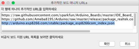
1. Arduino > Preferences… 의 메뉴에서 추가적인 보드매니저 URLs에 다음의 링크를 입력한다.

http://arduino.esp8266.com/stable/package_esp8266com_index.json

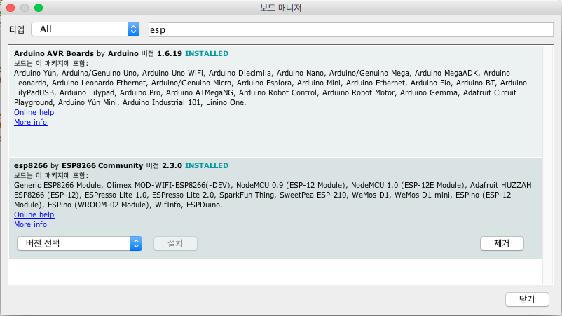
2. 툴 > 보드 > 보드 매니저… 의 메뉴의 필터에 ESP를 입력 후 esp8266을 선택후 설치한다.

Sming

맥에서는 https://github.com/SmingHub/Sming/wiki/MacOS-Quickstart 이 링크의 내용대로 따라하면 별 무리가 없다. 즉 이클립스, 툴체인, ESP SDK를 설치하고 Sming core를 빌드한다.

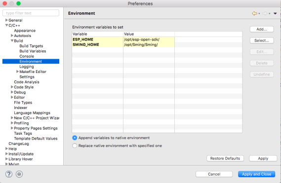
이클립스의 환경설정에서 SMING_HOME, ESP_HOME 설정을 한다.


SmingFramework의 Makefile-project.mk파일에서 ESPTOOL2의 경로를 다음과 같이 수정한다.

ESPTOOL2 ?= /opt/esp-open-sdk/utils/esptool2

Makefile-macos.mk파일에서 ESPTOOL의 경로를 다음과 같이 수정하고, COM_PORT항목도 환경에 맞게 수정한다.

ESPTOOL ?= $(ESP_HOME)/utils/esptool.py

Basic_Blink 프로젝트의 Makefile-user.mk파일도 다음과 같이 수정한다.

# Local build configuration

## Parameters configured here will override default and ENV values.

## Uncomment and change examples:

## Add your source directories here separated by space

MODULES = app

EXTRA_INCDIR = include

## ESP_HOME sets the path where ESP tools and SDK are located.

## Windows:

# ESP_HOME = c:/Espressif

## MacOS / Linux:

ESP_HOME = /opt/esp-open-sdk

## SMING_HOME sets the path where Sming framework is located.

## Windows:

# SMING_HOME = c:/tools/sming/Sming

## MacOS / Linux

SMING_HOME = /opt/sming/Sming

## COM port parameter is reqruied to flash firmware correctly.

## Windows:

# COM_PORT = COM3

## MacOS / Linux:

COM_PORT = /dev/tty.usbserial-A50285BI

## Com port speed

COM_SPEED= 115200

## Configure flash parameters (for ESP12-E and other new boards):

SPI_MODE = dio

## SPIFFS options

#DISABLE_SPIFFS = 1

SPIFF_FILES = files

Sming 프레임워크 소스코드를 불러와서 라이브러리를 빌드

  • Eclipse 실행
  • [File -> Import -> General -> Existing Project into Workspace] 선택
  • [Select root directory] 에서 SmingFramework 프로젝트 폴더를 선택
  • 프로젝트에서 Build

Blink 예제 빌드 확인

  • [File -> Import -> General -> Existing Project into Workspace] 선택
  • [Select root directory] Basic_Blink 프로젝트 폴더선택
  • 프로젝트에서 Build

프로젝트 빌드가 성공하면 [프로젝트 폴더\out\firmware] 폴더안에 *.bin 파일들이 생긴다.

참고


CREATOR Pro 보드 사용 및 분석

Rak Wireless사의 CREATOR Pro 보드는 Arduino Uno의 폼펙터를 가지며, RAK473 WiFi 모듈을 사용하고 NXP사의 LPC11U35를 사용해서 mbed에서도 프로그래밍이 가능하고, Arduino에서도 프로그래밍이 가능하다. WiKi에 나온 이 제품의 정보는 다음과 같은데, Realtek사의 Ameba RTL8710보드와 거의 동일하다.

CREATOR is a programmable platform for developing all kind of IoT applications. CREATOR is equiped with various peripheral interfaces, including Wifi, GPIO, I2C, UART, PWM, ADC. Through these interfaces, CREATOR can connect with electronic components such as LED, switches, manometer, hygrometer, PM2.5 dust sensors etc.
The collected data can be uploaded via WiFi, and be utilized by applications on smart devices to realize IoT implementation.
CREATOR and Arduino Uno have similar size, and the pins on CREATOR are compatible with Arduino Uno. CREATOR uses Micro USB to supply power, which is common in many smart devices.
Currently, CREATOR currently supports Windows XP/7/8 32 and 64 bits and MAC OS operating systems. In this example, please use Arduino IDE with version 1.6.7 or later.

LPC11U35의 역할

  • CMSYS-DAP가 내장
  • RAK473를 프로그래밍 및 디버깅이 가능하게 함
  • CMSYS-DAP 펌웨어는 JTAG을 통해서 업로드하고, 이후에는 CRP-DISABLED에 파일을 Copy하면 된다. 문제는 Mac에서 파일을 카피하면 안되고 윈도우즈에서만 된다. 관련자료
  • Tindie에서 $15에 판매하는 같은 기능을 갖는 외장형 보드

RAK473

Rak 홈페이지의 자료 및 Github의 자료

아두이노 개발 환경에서 사용법

추가적으로 함께 보면 좋은 자료


Jlink를 사용한 nRF51 flashing

지난번 nRF51개발 환경 포스팅에 빠진 부분인 flashing 부분

nrfjprog – Programming Tool

nrfjprog는 nRF5x-Command-Line-Tools의 번들 프로그램으로 SWD를 이용해 펌웨어 이미지를 로딩한다.

nrfjprog:

/* Optional: erase target if not already blank */
nrfjprog --family <nRF51/52> -e 
/* Load FW image to target */
nrfjprog --family <nRF51/52> --program _build/<name>.hex
/* Reset and run */    
nrfjprog --family <nRF51/52> -r

JlinkExe:

/* Open Jlink Commander from terminal in _build directory */ 
JLinkExe -device <nRF51/nRF52>
> erase // Optional: erase target if not already blank
> loadfile <name>.hex // loads FW
> r // Reset and halt
> g // Run
> q // Exit

JlinkExe -device nrf51822_xxaa -if swd -speed 4000


J-link 인터페이스

Segger사의 J-link 디버거는 JTAG과 SWD인터페이스를 제공한다.

JTAG  pin-out

SWD를 사용하기위해서는 위 20핀에서 필요한 4핀만 연결하면 된다. 여기서 VTref신호는 디버거에서 타겟보드의 전압을 체크하고 전압레퍼런스로 사용하기 때문에 타겟 보드의 전원을 연결하고, 프로그래밍을 할 MCU의 전압과 연결해야 한다. 그렇지 않을 경우 VTref is 0.xxxxV라고 에러메시지가 나면서 연결이 되지 않는다.

*참고로 J-link와 같은 디버거를 DIY형태로 개발을 해서 OSHW로 판매를 하는 것이 있다.  OSHChip_CMSIS_DAP_V1.0

참고: https://www.segger.com/interface-description.html


Puck.JS 사용법

FEATURES

  • Bluetooth Low Energy
  • Espruino JavaScript interpreter pre-installed
  • nRF52832 SoC – 64MHz Cortex M4, 64kB RAM, 512kB Flash
  • 8 x 0.1″ GPIO (capable of PWM, SPI, I2C, UART, Analog Input)
  • 9 x SMD GPIO (capable of PWM, SPI, I2C, UART)
  • ABS plastic rear case with lanyard mount
  • Silicone cover with tactile button
  • MAG3110 Magnetometer
  • IR Transmitter
  • Built in thermometer, light and battery level sensors
  • Red, Green and Blue LEDs
  • NFC tag programmable from JavaScript
  • Pin capable of capacitive sensing
  • Weight: 14g in plastic case, 20g in packaging
  • Dimensions of cardboard box: 64mm x 62mm x 16mm
  • Dimensions of plastic case: 36mm dia, 12.5mm thick
  • Dimensions of bare PCB: 29mm dia, 9mm thick

회로도 및 PCB Layout Eagle File

ON-BOARD LEDS, BUTTON AND GPIO

LEDs

  • Red LED on: digitalWrite(LED1,1), Off: digitalWrite(LED1,0)
  • LED2 : green, LED3: blue
  • LED1.write(1) or  LED1.write(0)
  • LED1.set(), LED1.reset()
  • 3개의 LED 한꺼번에 제어 digitalWrite([LED3,LED2,LED1], 7)

Button

  • digitalRead(BTN) or BTN.read()
  • 버튼 상태를 Polling 하는 것은 power 소모가 심하므로, setWatch 함수를 사용해서 버튼 상태가 바뀌는 것을 체크함.

    setWatch(function() { console.log(“Pressed”);}, BTN, {edge:”rising”, debounce:50, repeat:true});

GPIO pins

  • GPIO 핀은 D0 부터 D31까지.  digitalWrite/digitalRead 커맨드를 사용할 수 있고 PWM, I2C, SPI and Analog 사용 가능

ON-BOARD PERIPHERALS

  • Magnetometer
  • IR / Infrared
  • NFC – Near Field Communications
  • Light sensor
  • Bluetooth
  • Temperature
  • Battery level
  • Capacitive sense
  • SERIAL CONSOLE

FIRMWARE UPDATES

via nRF Toolbox App (Android & iOS)

  • On your Bluetooth LE capable phone, install the nRF Toolbox app
  • Download the latest espruino_xxx_puckjs.zip file from the binaries folder
  • Reset Puck.js with the button held down – the Green LED should be lit
  • Release the button within 3 seconds of inserting the battery – the Red LED should light instead. If it doesn’t, you’ll need to try again, holding the button down for less time after inserting the battery.
  • Open the nRF Toolbox app
  • Tap the DFU icon
  • Tap Select File, choose Distribution Packet (ZIP), and choose the ZIP file you downloaded
  • Tap Select Device and choose the device called DfuTarg
  • Now tap Upload and wait. The LED should turn blue and the DFU process will start – it will take around 90 seconds to complete

Espruino IDE 사용하기

  • Web Bluetooth 사용 설정: Mac에서 BLE가 지원되는지 확인하는 법은 “이 Mac에 관하여” > 시스템 리포트 > 하드웨어 > Bluetooth 항목아래 ” Bluetooth 저에너지 기술이 지원됨” 이 “예”라고 표시되어 있는지 확인한다.
  • 크롬에서 주소표시줄에 chrome://flags를 입력하고, ” #enable-web-bluetooth” 항목을 사용하도록 설정하고 브라우저를 다시 시작함.
  • https://www.espruino.com/ide/ 에서 Web IDE를 시작한다.
  • Web IDE에서 연결 버튼을 클릭하고, Port설정에서 Web Bluetooth를 선택한다.

참고: https://www.espruino.com/Puck.js+Quick+Start


피지컬 웹 (Physical Web)

IoT 디바이스에 접급을 위해서 앱이 필요한 경우가 있는데, 이럴 경우 디바이스마다 앱이 존재하게 된다. 구글에서는 이걸 웹에서 해결하겠다는 접근이 피지컬 웹(Physical Web)이다. 이렇게 할 때의 장점은 디바이스에는 적은 기능만 넣고, 나머지는 웹쪽에서 구현을 하겠다는 의미이다. 이때 IoT 디바이스(비콘)가 자신의 URL을 주기적으로 Broadcasting하기만 하면 된다.
관련 정보
https://github.com/google/physical-web


Mac OS X에 nRF51 개발 환경 설정하기

1. gcc 설치
여기에서 다운로드 한다.

$ mkdir /usr/local/gcc-arm
$ tar -xjf gcc-arm-none-eabi-5_4-2016q3-20160926-mac.tar.bz2 -C /usr/local/gcc-arm

2. nRF5x-Command-Line-Tools-OSX
여기에서 다운로드 한다.
/usr/local/ 에 nrfjprog와 mergehex를 copy한다.

3. .bash_profile 수정

export PATH=/usr/local/bin:/usr/local/sbin:/usr/local/nrfjprog:$PATH

4. Segger Software and documentation pack for Mac OS X 설치
여기에 패키지 파일이 있다.

5. SDK설치 및 Makefile.posix 파일 수정
여기 또는 여기에서 SDK를 다운로드 해서 원하는 곳에서 압축을 푼다.
components/toolchain/gcc/Makefile.posix 이 파일을 gcc 버전에 맞게 수정한다.

GNU_INSTALL_ROOT := /usr/local/gcc-arm/gcc-arm-none-eabi-5_4-2016q3
GNU_VERSION := 5.4.1
GNU_PREFIX := arm-none-eabi

6. 컴파일 및 확인
example 폴더 아래에서 make해서 hex 파일이 생성되는지 확인한다.

$ make

7. 보드와 연결해서 다운로드가 되는지 확인한다.

$ make flash

Nordic에서 출시한 보드

PCA10028

PCA10031

참고
https://devzone.nordicsemi.com/blogs/22/getting-started-with-nrf51-development-on-mac-os-x/
https://aaroneiche.com/2016/06/01/programming-an-nrf52-on-a-mac/
http://www.nordicsemi.com/eng/Products/Bluetooth-low-energy/nRF51822
Getting started with the nRF5 development kit
https://devzone.nordicsemi.com/tutorials/


아두이노에서 ESP8266 사용하기

아두이노에서 ESP8266 사용하기

  • 아두이노 IDE는 1.6.4 이상의 버전을 설치
  • 아두이노의 환경설정에서 추가적인 보드매니저 URLs에 다음과 같이 입력

http://arduino.esp8266.com/stable/package_esp8266com_index.json

  • 툴 > 보드매니저에서 ESP8266을 검색후 ESP8266 보드를 설치한다.

arduino_board_maneger

  • 설치후 툴 > 보드 메뉴에서 가지고 있는 ESP8266보드를 선택한다.

핀레이아웃

간단한 Blink Test


Pages:1234